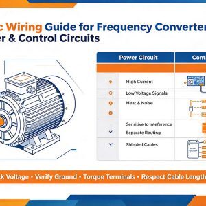
A frequency converter, often called a variable frequency drive or VFD, controls motor speed by changing the frequency and voltage supplied to the motor. A sound wiring approach separates power circuits from control circuits, protects the drive and motor, and reduces electrical noise that can cause unreliable operation. This Basic Wiring Guide for Frequency Converter Power & Control Circuits explains the main wiring areas, practical layout rules, and checks to make before energizing a system.
What does frequency converter wiring include?
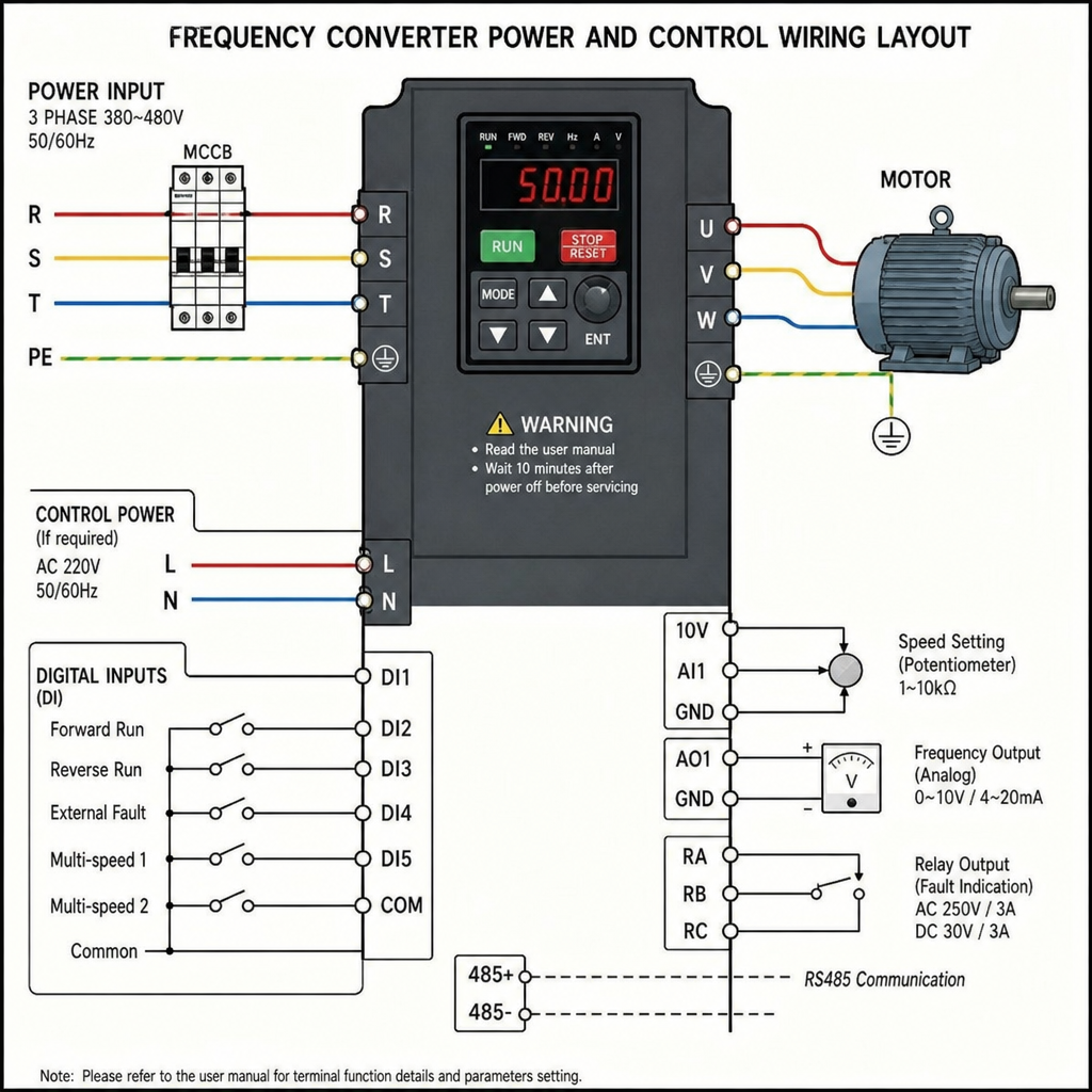
Frequency converter wiring includes two main groups: the power circuit that carries high current to and from the drive, and the control circuit that carries low-voltage signals for commands, feedback, and interlocks. The power side typically connects the incoming supply, protective devices, the converter input terminals, and the motor output terminals. The control side connects devices such as start/stop push buttons, selector switches, sensors, relays, analog speed references, communication cables, and safety interlocks.
Understanding this split matters because the two groups behave differently. Power wiring produces heat, magnetic fields, and electrical noise, especially between the converter and motor. Control wiring is more sensitive and can pick up interference if it is routed too close to motor leads or high-current conductors.
Core safety and planning principles
Before wiring, review the converter manual, motor nameplate, panel drawings, and applicable electrical codes. Drive terminals, ratings, grounding requirements, and braking connections can vary by model, so the manual is the primary reference for terminal names and permitted wiring methods. If the installation affects machinery safety or uses line voltage, a qualified electrician or controls professional should verify the design.
Good planning reduces troubleshooting later. Confirm the supply voltage and phase, motor full-load current, enclosure environment, wire sizes, overcurrent protection, grounding path, and cable routing before cutting or terminating conductors. Leave enough panel space for heat dissipation and service access, and label wires so future maintenance is safer and faster.
Use this pre-wiring checklist:
- Confirm converter input voltage, phase, and current rating match the supply.
- Confirm the motor voltage, frequency, and current are compatible with the converter.
- Identify input, output, ground, control, analog, and communication terminals.
- Plan separate routes for power wiring and low-voltage control wiring.
- Select shielded motor cable when required by the application or manufacturer.
- Provide proper disconnecting means, fusing, circuit breakers, and overload settings.
- Verify that emergency-stop and safety circuits meet the machine’s risk requirements.
Power circuit wiring fundamentals
The power circuit normally begins at the supply source and passes through a disconnect, protection device, and any required line reactor or filter before reaching the converter input. From the converter output, the wiring goes directly to the motor terminals. In many installations, output contactors, long cable runs, or shared conduits can create problems unless specifically allowed and designed for the drive.
Incoming supply connections
Input terminals are commonly marked for line power, but exact labels differ by manufacturer. Keep the incoming supply conductors sized for the load and installation conditions, and terminate them firmly according to the specified torque. Loose terminals create heat and intermittent faults, while undersized conductors can lead to voltage drop and nuisance trips.
If the converter requires a specific grounding system, input filter, or line reactor, install it as specified. Drives can create harmonic currents and switching noise, so upstream equipment should be selected with the converter in mind rather than treated like a simple motor starter.
Motor output connections
The motor output terminals feed a switched waveform from the converter. These conductors should run only to the controlled motor, not to lighting, outlets, control devices, or unrelated loads. Avoid connecting power-factor correction capacitors or surge devices on the converter output unless the manufacturer specifically permits them.
For longer motor cable runs, follow the converter manual for cable type, maximum distance, output reactors, or dv/dt filters. Long runs can increase reflected-wave voltage stress at the motor and may affect bearing life or insulation performance. Keeping motor leads short, shielded, and properly grounded is often the most practical first step.
Control circuit wiring fundamentals
Control circuits tell the converter what to do. They may use dry contacts, transistor outputs, relay outputs, analog inputs, analog outputs, or digital communication. Because these circuits usually carry low voltage and low current, they should be routed and protected as signal wiring, not bundled with motor power wiring.
Typical control connections include:
- Start and stop commandsfrom push buttons, selector switches, PLC outputs, or remote relays.
- Forward and reverse selectionwhen the application permits two-direction operation.
- Speed reference signalsfrom a potentiometer, analog output, keypad, or communication network.
- Fault and run feedbackto a pilot light, PLC input, or monitoring system.
- Interlock signalsfrom guards, pressure switches, thermal switches, or process devices.
Digital inputs usually respond to on/off commands. Analog inputs accept variable speed references, commonly from voltage or current signals depending on the converter settings. Match the wiring to the selected parameter mode; a correctly landed wire can still fail if the input is configured for the wrong signal type.
How should power and control wires be separated?
Power and control wires should be physically separated so high-current switching noise does not disturb low-voltage signals. In practice, route incoming line wiring, motor wiring, control wiring, and communication wiring in separate ducts or conduits where possible. When they must cross, cross at right angles rather than running them in parallel for long distances.
Shielding and grounding are also important. For motor cables, bond the shield or grounding conductor according to the drive manufacturer’s instructions, usually with a low-impedance path back to the drive or panel ground. For analog and communication cables, use the recommended shield termination method and avoid creating unnecessary ground loops.
A simple separation plan looks like this:
| Wiring type | Main concern | Practical routing habit |
| Incoming power | Current, heat, protection | Keep short, protected, and away from signals |
| Motor output | Switching noise | Route separately and use approved cable |
| Digital control | False starts or stops | Keep away from motor leads and label clearly |
| Analog signals | Speed instability | Use shielded cable and avoid parallel power runs |
| Communications | Data errors | Follow network cable and grounding rules |
Grounding, shielding, and noise control
Grounding is not only for fault protection; it also gives electrical noise a controlled path. Connect the converter protective earth terminal, motor frame, enclosure, and supply grounding conductor as required by the design and local code. Do not rely on conduit alone unless it is approved and installed as an effective grounding path.
Noise problems often appear as erratic speed commands, random faults, unstable analog readings, or communication dropouts. Many of these issues come from poor routing, missing shields, loose grounds, or mixing control and motor wiring in the same raceway. Solve the physical wiring issues first before masking the symptoms with parameter changes.
Parameter setup after wiring
Wiring and programming work together. After the conductors are landed, set the motor data, control source, speed reference source, acceleration and deceleration times, minimum and maximum frequency, input functions, and output functions. If a drive is wired for terminal control but programmed for keypad control, the start button will not behave as expected.
Before running the motor at full speed, perform a controlled test. Verify that the drive powers up without faults, the stop command works, direction is correct, and the speed reference changes smoothly. If the motor rotates the wrong way, follow the manufacturer’s safe procedure for correcting phase sequence on the motor output.
Common wiring mistakes to avoid
Many converter faults come from simple wiring errors. The most damaging mistake is connecting supply power to the output terminals, which can destroy the drive. Another common issue is switching the motor leads while the drive is running, which may create overvoltage, overcurrent, or output-stage stress.
Avoid these frequent problems:
- Routing analog signal cable in the same conduit as motor cable.
- Forgetting to connect the motor ground or cable shield.
- Using one converter to feed multiple motors without proper design.
- Setting control parameters before confirming the actual wiring method.
- Leaving wire strands loose at terminals or failing to torque connections.
- Ignoring manufacturer limits for motor cable length.
- Bypassing safety interlocks through normal start/stop inputs.
Final inspection before energizing
A final inspection should be slow, methodical, and documented. Check each conductor against the drawing, tug lightly on terminals, inspect insulation, confirm grounding, and verify that no metal chips or wire scraps remain in the panel. Use a meter to confirm supply voltage before applying power to the converter.
Once energized, start with no load or the safest available operating condition if the machine design allows it. Watch for abnormal noise, vibration, heating, alarms, or unstable speed. A clean installation is not just neat; it makes the frequency converter easier to commission, safer to maintain, and more reliable over the life of the equipment.