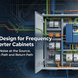
Cabinet-mounted frequency converters are powerful, compact, and essential in modern motor control systems, but they can also become a major source of electromagnetic noise if the cabinet is not designed carefully. A practical EMC approach combines layout discipline, grounding, cable management, shielding solutions, filtering, and reliable installation habits. When these elements work together, the result is stronger electromagnetic compatibility, better signal stability, and fewer unexpected faults in the field.
Why does EMC matter in cabinet-mounted frequency converters?
EMC matters because a frequency converter switches voltage and current at high speed, creating conducted and radiated interference that can disturb sensors, PLCs, communication lines, control boards, and nearby equipment. Good EMC Anti-interference Design for Cabinet-mounted Frequency Converters reduces those risks before they become nuisance trips, communication errors, inaccurate feedback, or unstable machine behavior.
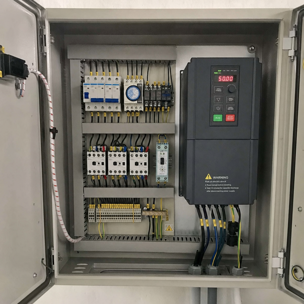
In a cabinet, the converter is rarely alone. It often shares space with power supplies, contactors, relays, terminal blocks, I/O modules, safety circuits, and communication devices. Without a deliberate design, noise can travel through cables, cabinet panels, grounding paths, and even small gaps between conductive surfaces.
The goal is not simply to “block noise” after installation. The better strategy is to control how interference is generated, how it couples into other circuits, and how it returns to its source. This is where interference mitigation becomes a system-level design task rather than a last-minute accessory choice.
The main interference paths inside a converter cabinet
Electromagnetic interference usually spreads through several paths at once. Understanding these paths helps engineers choose the right emi protection methods instead of applying filters, ferrites, or shields randomly.
Common interference paths include:
- Conducted noise on power lines:Switching activity can travel along input and output cables, affecting the supply network or connected devices.
- Radiated noise from cables and components:Long motor cables, unshielded conductors, and poor routing can act like antennas.
- Capacitive coupling:High-voltage cables placed close to signal cables can inject unwanted voltage into low-level circuits.
- Inductive coupling:High-current loops can induce noise into nearby wiring, especially when cables run in parallel.
- Ground loops and poor bonding:Inconsistent grounding can create unwanted current paths and voltage differences across the cabinet.
A strong EMC design reduces loop areas, separates noisy and sensitive circuits, and provides low-impedance return paths for high-frequency currents. These principles are more reliable than relying on one component to solve every problem.
Cabinet layout sets the foundation for noise control
The physical layout of the cabinet has a major influence on EMC performance. A clean layout keeps power conversion noise away from low-level control and communication circuits. It also makes grounding, shielding, and maintenance easier throughout the life of the equipment.
Start by dividing the cabinet into functional zones. High-power components such as frequency converters, braking units, contactors, reactors, and motor terminals should be grouped away from PLCs, analog input modules, encoders, and communication gateways. If the cabinet size allows, use separate wiring ducts for power, control, and communication cables.
Cable crossing is sometimes unavoidable. When power and signal cables must cross, they should cross at roughly 90 degrees rather than running side by side. Parallel runs increase coupling, especially over long distances. Even small improvements in routing can create meaningful noise reduction methods without adding extra hardware.
Ventilation should also be considered carefully. Heat dissipation is necessary, but large openings, poorly bonded panels, or loosely fitted covers can weaken the cabinet’s shielding performance. The design should balance thermal management with the need for a continuous conductive enclosure.
Grounding and bonding create the return path
Grounding is often misunderstood as a simple safety connection. In EMC design, grounding and bonding also provide a low-impedance path for high-frequency noise currents. If that path is weak, long, painted, corroded, or inconsistent, noise may return through signal wiring or other unintended routes.
The mounting plate should be conductive and well bonded to the cabinet frame. Frequency converters, filters, reactors, shield clamps, and grounding bars should have short, wide, low-impedance connections to this reference plane. For high-frequency interference, a wide metal contact is usually more effective than a long thin wire because impedance rises with length and frequency.
Painted surfaces can prevent good electrical contact. Where bonding is required, remove paint or use suitable hardware that ensures metal-to-metal contact. Hinged doors that hold operator panels or control devices may also need bonding straps, especially when sensitive electronics or cable shields terminate nearby.
A well-planned grounding system improves safety, supports electromagnetic compatibility, and gives other EMC measures a stable foundation. Without good bonding, even high-quality filters and shielding solutions may perform below expectations.
How should cables and shields be handled?
Cables and shields should be treated as active parts of the EMC design, not just as accessories. Motor cables, encoder lines, analog signals, and communication cables each need suitable routing, termination, and separation so that noise currents stay controlled.
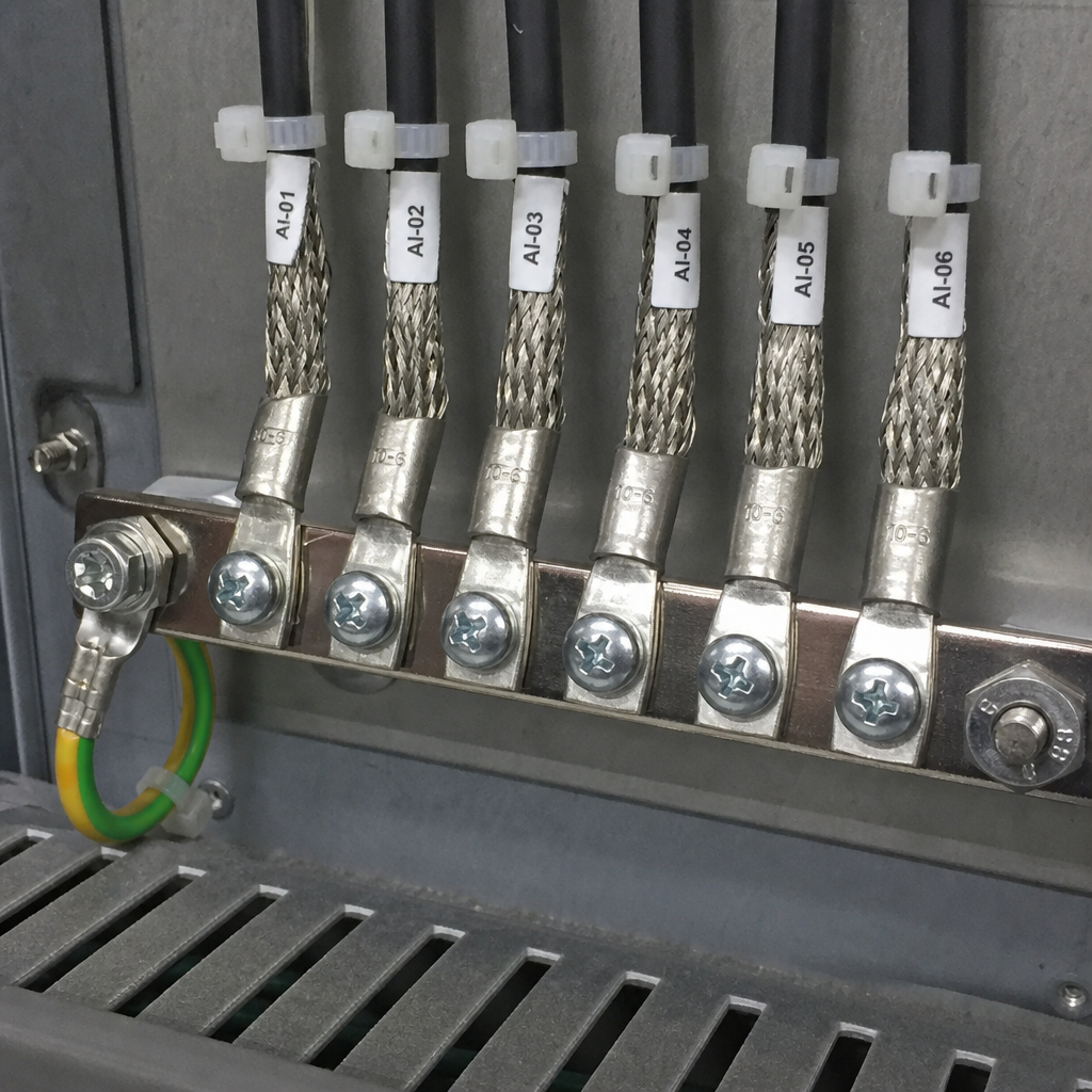
For motor outputs, shielded cable is commonly used because the converter output contains fast switching edges. The cable shield should usually be terminated with a broad 360-degree connection at the cabinet entry or near the converter, depending on the equipment design and manufacturer guidance. A short pigtail connection may be convenient, but it often performs poorly at high frequencies.
Signal cables require different care. Analog and encoder wiring should be kept away from motor leads, braking resistor cables, and input power conductors. Twisted pairs help reduce loop area, while shielded twisted pairs provide additional protection where signals are low-level or noise-sensitive.
Communication networks also need disciplined installation. Follow the network’s termination, grounding, and cable specifications. Mixing power and data conductors in the same duct, leaving shields floating without a clear reason, or creating multiple uncontrolled ground paths can lead to intermittent faults that are difficult to diagnose.
Cable practices that support signal integrity solutions:
- Route motor and braking cables separately from control and communication cables.
- Keep noisy cables short where possible, especially between converter and motor.
- Use 360-degree shield termination for high-frequency performance.
- Avoid long shield pigtails unless the equipment design specifically calls for them.
- Cross power and signal cables at right angles when separation cannot be maintained.
- Label shield termination points so future maintenance does not compromise the design.
Filtering and suppression reduce conducted interference
Filters, reactors, and suppression devices are important tools, but they work best when selected and installed as part of a complete EMC strategy. An input EMC filter can reduce conducted noise returning to the supply. Line reactors may help manage current distortion and limit certain electrical stresses. Output reactors, sine filters, or dv/dt filters may be considered when cable lengths, motor insulation, or application conditions require extra protection.
Placement matters. A filter mounted far from the frequency converter, connected with long unshielded leads, may lose much of its effectiveness. The wiring from the filter to the converter should be short, direct, and separated from unfiltered cables. If the filtered and unfiltered conductors run together, noise can couple back across the layout and bypass the filter’s purpose.
Suppression should also be applied to relays, contactors, solenoids, and other switching devices in the same cabinet. Coils and inductive loads can generate transients that disturb control circuits. Suitable surge suppressors, RC snubbers, varistors, or flyback diodes can reduce those events when chosen correctly for the circuit type.
These noise reduction methods do not replace good layout and bonding. Instead, they refine the design by controlling conducted emissions and reducing the chance that one circuit will disturb another.
Shielding turns the cabinet into part of the EMC system
The cabinet enclosure can act as a protective barrier when it is conductive, continuous, and well bonded. This makes the cabinet itself one of the most important shielding solutions in the system. However, shielding performance depends on details that are easy to overlook.
Doors, side panels, gland plates, and removable covers should maintain reliable electrical continuity. Cable entry points should be planned so shields can be bonded close to where cables enter the cabinet. If shielded cables pass through plastic glands with no proper termination, the enclosure may no longer control radiated emissions effectively.
Openings for ventilation, displays, pushbuttons, and cable glands should be designed with EMC in mind. Large gaps can reduce shielding effectiveness, especially at higher frequencies. Where sensitive equipment is installed nearby, it may be worth using conductive gaskets, EMC glands, or segregated compartments to preserve the enclosure’s protective function.
Good shielding is not about making the cabinet visually sealed. It is about creating a controlled conductive boundary that redirects unwanted high-frequency energy safely and predictably.
Practical EMC design checklist for converter cabinets
A checklist helps turn EMC theory into repeatable design and installation habits. The following points can be used during cabinet planning, assembly, inspection, or troubleshooting.
- Separate functional zones early.Keep frequency converters and high-current switching devices away from PLCs, analog modules, and communication equipment.
- Use short, direct grounding paths.Bond converters, filters, mounting plates, doors, and shield bars with low-impedance connections.
- Control cable routing.Separate input power, motor output, braking, control, analog, and data cables as much as the cabinet allows.
- Terminate shields properly.Use broad shield contact methods, especially for motor cables and high-frequency noise paths.
- Install filters correctly.Keep leads short and prevent filtered and unfiltered conductors from being routed together.
- Suppress switching transients.Add suitable protection to coils, relays, and inductive devices that can inject noise into the cabinet.
- Preserve cabinet continuity.Check panel bonding, gland plates, door straps, and metal-to-metal contact points.
- Document the EMC layout.Future maintenance teams should understand which cable routes, shield clamps, and bonding points are intentional.
This type of checklist is especially useful because many EMC problems are created after the original design, during panel modifications or field servicing. Clear documentation helps protect the design from gradual degradation.
Testing, troubleshooting, and continuous improvement
Even a carefully designed cabinet should be checked during commissioning. Visual inspection comes first: look for long shield pigtails, mixed cable routes, loose bonding hardware, ungrounded doors, or filters wired with excessive lead length. Many interference problems are visible once the design intent is known.
Functional testing should then focus on symptoms. Watch for communication dropouts, unexplained drive trips, unstable analog values, encoder errors, or control resets when the motor starts, stops, or changes speed. These patterns often point to coupling between power switching and sensitive circuits.
Troubleshooting should be systematic. Change one variable at a time, such as cable routing, shield termination, filter placement, or grounding connection quality. Randomly adding components can mask the real cause and make the final installation harder to maintain.
When the application is complex or must meet formal EMC requirements, laboratory testing or specialist review may be appropriate. Still, the strongest results usually begin with the basics: cabinet layout, bonding, cable discipline, filtering, and shielding done correctly from the start.
A reliable EMC strategy is built into the cabinet
Effective EMC design for cabinet-mounted frequency converters is not a single product or final inspection step. It is a design discipline that begins with layout and continues through grounding, shielding, filtering, cable routing, testing, and maintenance.
By combining practical interference mitigation with reliable signal integrity solutions, engineers can reduce faults, improve equipment stability, and make future troubleshooting easier. The best cabinet designs treat every cable, panel, bond, and filter as part of one connected EMC system.