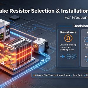
A brake resistor helps a frequency drive handle energy that flows back from a decelerating motor. When selected and installed correctly, it can reduce DC bus overvoltage trips, support controlled stopping, and protect the drive from avoidable stress. This resistor selection guide explains the practical relationship between resistance, wattage, braking duty, wiring, and safe installation.
How do you choose the right brake resistor for a frequency drive?
Choose a brake resistor by confirming the drive manufacturer’s allowable resistance range, estimating how much braking energy the load will generate, and selecting a wattage rating that can absorb that energy without overheating. The key is to size both electrical resistance and thermal capacity; one controls braking current, while the other controls heat dissipation over time.
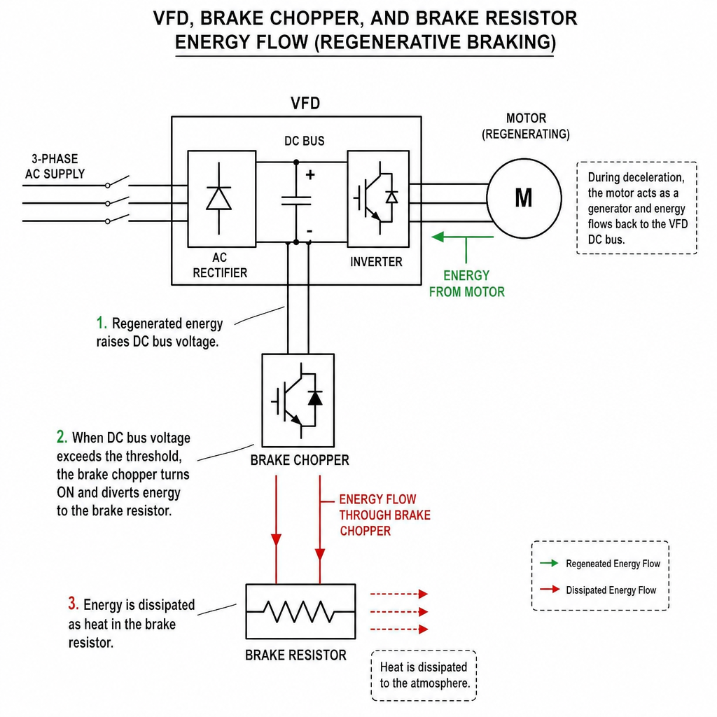
A VFD brake circuit usually includes a brake chopper transistor that switches excess DC bus energy into the resistor. That chopper has a current limit. For that reason, the resistor must never be below the minimum ohm value specified for the drive, even if a lower resistance looks attractive for faster stopping.
For OEM-specific work, such as SEW brake resistor selection, use the drive manual and resistor tables as the controlling reference. General sizing logic is useful, but the final choice should match the drive’s voltage class, brake chopper rating, duty cycle, and approved wiring requirements.
Resistance controls braking current and stopping force
Resistance, measured in ohms, sets the peak braking current when the brake chopper turns on. Lower resistance allows more current to flow, which can increase braking torque and shorten deceleration time. Higher resistance limits current, which may make braking gentler but can also leave the drive unable to remove regenerated energy quickly enough.
This is where many brake resistor sizing mistakes happen. A resistor with too high an ohm value may not provide enough braking effect, so the drive still trips on overvoltage during rapid deceleration. A resistor with too low an ohm value may overload or damage the brake chopper transistor.
A simple comparison shows the tradeoff. On a 575 V, 10 HP drive, a 35 Ω resistor can provide stronger peak braking than a 63 Ω resistor of the same wattage because it allows higher braking current. However, if both are rated 3000 W, their continuous heat-handling ability is similar; the lower resistance does not automatically mean the resistor can absorb more heat over repeated stops.
Wattage defines how much braking heat the resistor can handle
Wattage is the resistor’s thermal capacity. It indicates how much braking energy can be converted into heat over a given duty cycle without exceeding safe temperature limits. A machine that stops once every few minutes may need a very different resistor than one that indexes, lowers, reverses, or decelerates constantly.
Think of resistance as the “how hard can it brake right now?” value, and wattage as the “how often can it keep doing that?” value. If the wattage is too low, the resistor may overheat even though the drive initially stops well. If the resistance is correct but thermal capacity is undersized, problems may appear only after several cycles.
A practical estimate starts with the kinetic energy in the motor and load. In simplified terms, more inertia and higher speed create more stored energy. Dividing the braking energy by the deceleration time gives average braking power, and the application duty cycle determines whether the resistor needs intermittent or higher continuous capacity.
A practical brake resistor sizing checklist
Use this checklist before ordering or installing a resistor:
- Confirm the drive voltage class and brake option.Not every drive has an internal braking transistor, and some require an external brake module.
- Find the minimum permitted resistance.This is the lowest safe ohm value for the drive’s brake chopper. Do not go below it.
- Estimate braking energy.Consider motor power, load inertia, operating speed, and how quickly the machine must stop.
- Calculate or estimate average braking power.Shorter deceleration times increase the power the resistor must absorb.
- Review stopping frequency.Occasional emergency stops create different heating conditions than frequent production stops.
- Apply ambient and enclosure derating.A hot cabinet or poor airflow reduces usable resistor capacity.
- Check approvals and manufacturer tables.For drive families with published combinations, follow the approved resistor selection guide.
Parallel resistor banks can be useful when you need a lower effective resistance or higher total wattage. However, parallel wiring also increases peak current demand on the brake chopper. The resulting resistance must still remain within the drive’s allowable range.
What happens when the resistor is the wrong size?
If the resistor is too high in resistance, braking current is limited and the drive may not be able to control DC bus voltage during deceleration. If it is too low in resistance, the brake chopper may be forced beyond its current capability. If wattage is too low, the resistor may overheat during repeated stops even when the ohm value is correct.
Common symptoms include nuisance overvoltage faults, longer-than-expected stopping times, hot resistor housings, tripped thermal switches, or drive brake transistor alarms. These symptoms do not always mean the resistor alone is wrong. Drive parameters, deceleration ramps, load changes, and wiring issues can create similar behavior.
When troubleshooting, start with the basics. Confirm the actual installed resistance with power safely isolated, compare it to the drive manual, inspect wiring terminals, and review the programmed deceleration time. Then check whether the machine’s real stopping frequency matches the assumptions used during selection.
Installation details that protect the drive and resistor
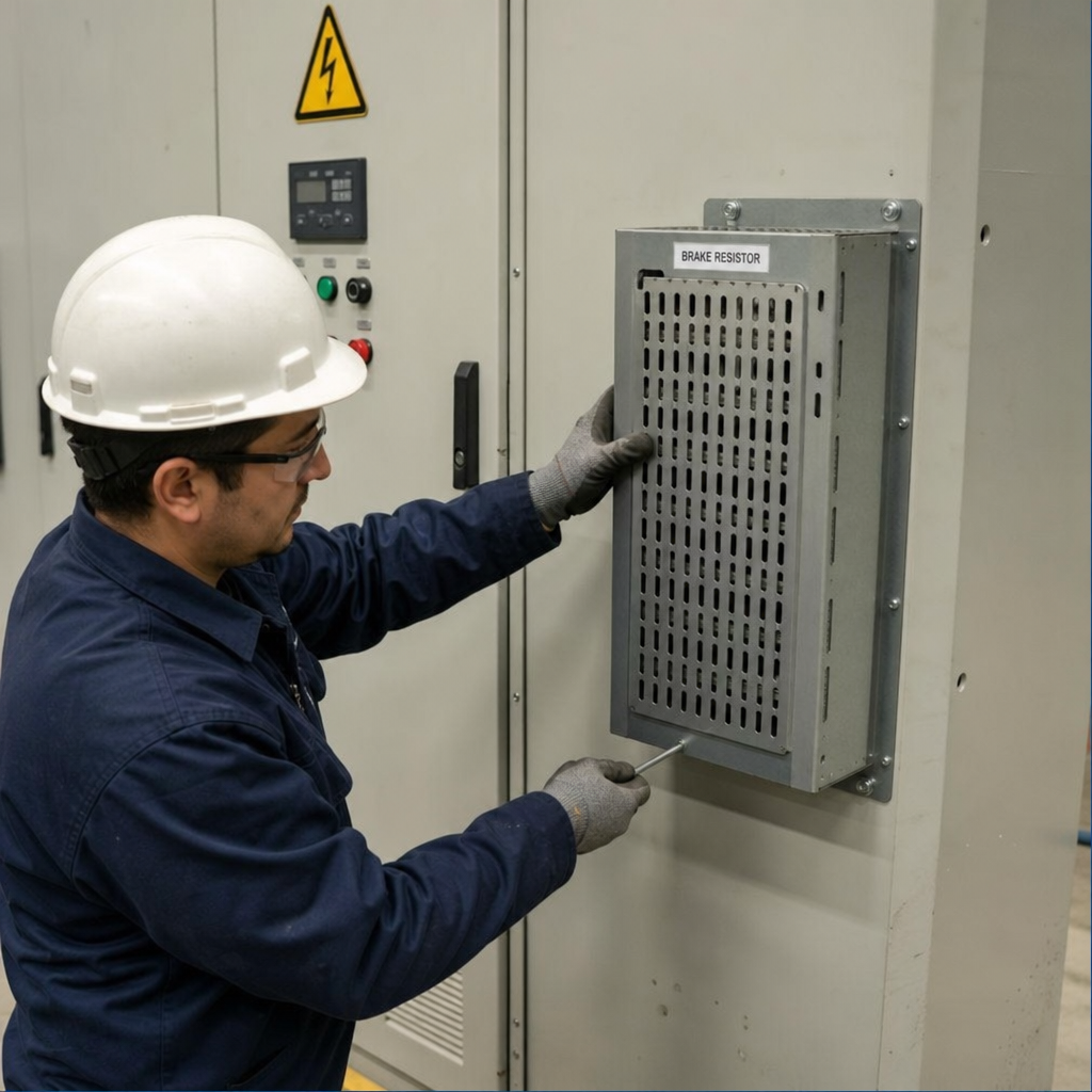
A brake resistor gets hot by design, so installation is not just an electrical task. Mount it where heat can dissipate safely, with clearance around the housing and away from temperature-sensitive components. Follow the resistor manufacturer’s orientation and spacing requirements rather than treating it like an ordinary control component.
Wiring should be sized for braking current and routed to reduce electrical noise. Keep leads as short as practical, tighten terminals correctly, and use shielding or separation where the drive manufacturer recommends it. Long, poorly routed brake wiring can contribute to electromagnetic interference and unreliable operation.
Thermal protection is strongly recommended. Many resistor assemblies include or support a thermal switch that can be wired into the drive enable circuit, fault input, or safety-related control scheme as appropriate for the machine design. The goal is simple: if the resistor overheats, the system should stop demanding braking before damage occurs.
Brake resistors are not the only braking option
Dynamic braking with a resistor is common because it is relatively straightforward and effective for many stopping applications. It converts regenerated motor energy into heat, which is acceptable when stops are intermittent and the heat can be managed.
Regenerative drives are different because they can return energy to the supply instead of burning it off as heat. They may make sense for applications with frequent braking, overhauling loads, or energy-saving goals, though they require different equipment and system considerations. Mechanical brakes are also useful, but they are typically used for holding, parking, or safety functions rather than absorbing all deceleration energy from a running load.
For many machines, the best solution combines correct drive ramp settings, a properly sized resistor, and mechanical braking only where it is intended. That balance improves reliability without asking one component to do a job it was not designed to handle.
Key takeaways for reliable dynamic braking
Brake resistor selection is a two-part decision: ohms determine braking current, while watts determine heat capacity. Lower resistance can improve stopping performance, but only within the drive’s brake chopper limits. Higher wattage supports longer or more frequent braking, but it does not compensate for an ohm value that is wrong for the drive.
Before finalizing a Brake Resistor Selection & Installation Guide for Frequency Drives project, verify the manufacturer’s data, calculate realistic braking duty, and plan the installation as carefully as the sizing. Good brake resistor sizing prevents nuisance trips, protects the VFD, and helps the machine stop consistently under real operating conditions.