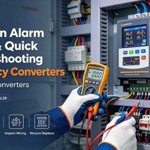
Frequency converter alarms are designed to protect the drive, motor, process, and people around the equipment. The fastest way to respond is to read the code, make the area safe, check the simple external causes first, and only then suspect internal drive hardware. This guide to Common Alarm Codes & Quick Troubleshooting for Frequency Converters focuses on practical field diagnosis, with examples commonly seen on Danfoss VLT® drives.
What should you do first when a frequency converter trips?
Start by making the system safe, recording the alarm exactly as shown, and checking the drive manual before resetting anything. Danfoss specifically recommends having the correct instruction manual, programming guide, and service manual available during troubleshooting, because alarm behavior and parameters vary by model and frame size. (danfoss.com)
Before opening panels, follow site lockout/tagout procedures and allow the DC bus to discharge according to the equipment documentation. A reset without inspection can restart the process into the same fault condition, and repeated trips can turn a wiring, cooling, or load issue into a drive failure.
A good first pass looks like this:
- Record the code and operating state: speed reference, load condition, recent maintenance, and whether the trip happened at start, acceleration, steady run, or stop.
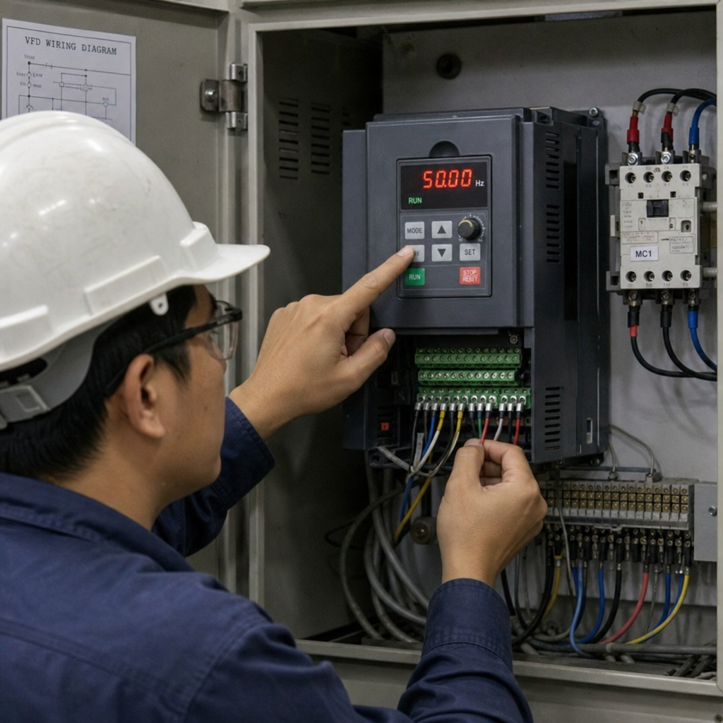
- Inspect the obvious: loose terminals, blown fuses, overheated components, blocked filters, damaged motor cables, and water or dust contamination.
- Measure before replacing parts: verify incoming phase-to-phase voltage, motor lead condition, grounding, and control signals.
- Reset only once the cause is addressed: if the alarm returns immediately, stop and isolate the fault instead of repeatedly cycling power.
Quick-reference table for common alarm codes
| Alarm code | What it usually means | First checks | Likely next action |
| AL2 / Warning-Alarm 2: Live zero error | A programmed analog input signal is below the expected minimum | Check 4–20 mA or 2–10 V wiring, signal source, input scaling, and terminal settings | Repair broken signal wiring or correct parameter/switch setup |
| AL4 / Warning-Alarm 4: Mains phase loss | Missing input phase, high mains imbalance, or possible input rectifier fault | Measure all input phases, check fuses, contactor, disconnect, and line terminals | Correct supply issue; investigate rectifier if input power is balanced |
| AL7: DC link overvoltage | DC bus voltage is too high, often during deceleration or regeneration | Check incoming voltage, deceleration time, braking resistor, and brake chopper | Lengthen decel ramp or repair braking circuit as applicable |
| AL13: Overcurrent | Current surge or current above drive limit | Inspect motor cable, motor insulation, load jam, acceleration time, and IGBT condition | Disconnect motor test; repair motor/cable or drive power stage |
| AL29: Heat sink temperature | Drive cooling system or ambient condition problem | Check fan operation, heatsink, filters, cabinet ventilation, and load | Clean cooling path, replace fan, reduce heat/load |
The codes below are common examples, especially in Danfoss VLT troubleshooting contexts. Always confirm the exact meaning in the manual for the installed model.
Danfoss documentation describes Alarm 4 as a missing supply phase, excessive mains imbalance, or possible input rectifier fault, and recommends checking supply voltage and current to the drive. (assets.danfoss.com) Danfoss service material also identifies Alarm 13 as overcurrent and points technicians toward current surge conditions, while Danfoss support content notes Alarm 29 is tied to heatsink temperature limits. (danfoss.com)
The practical troubleshooting sequence that saves time
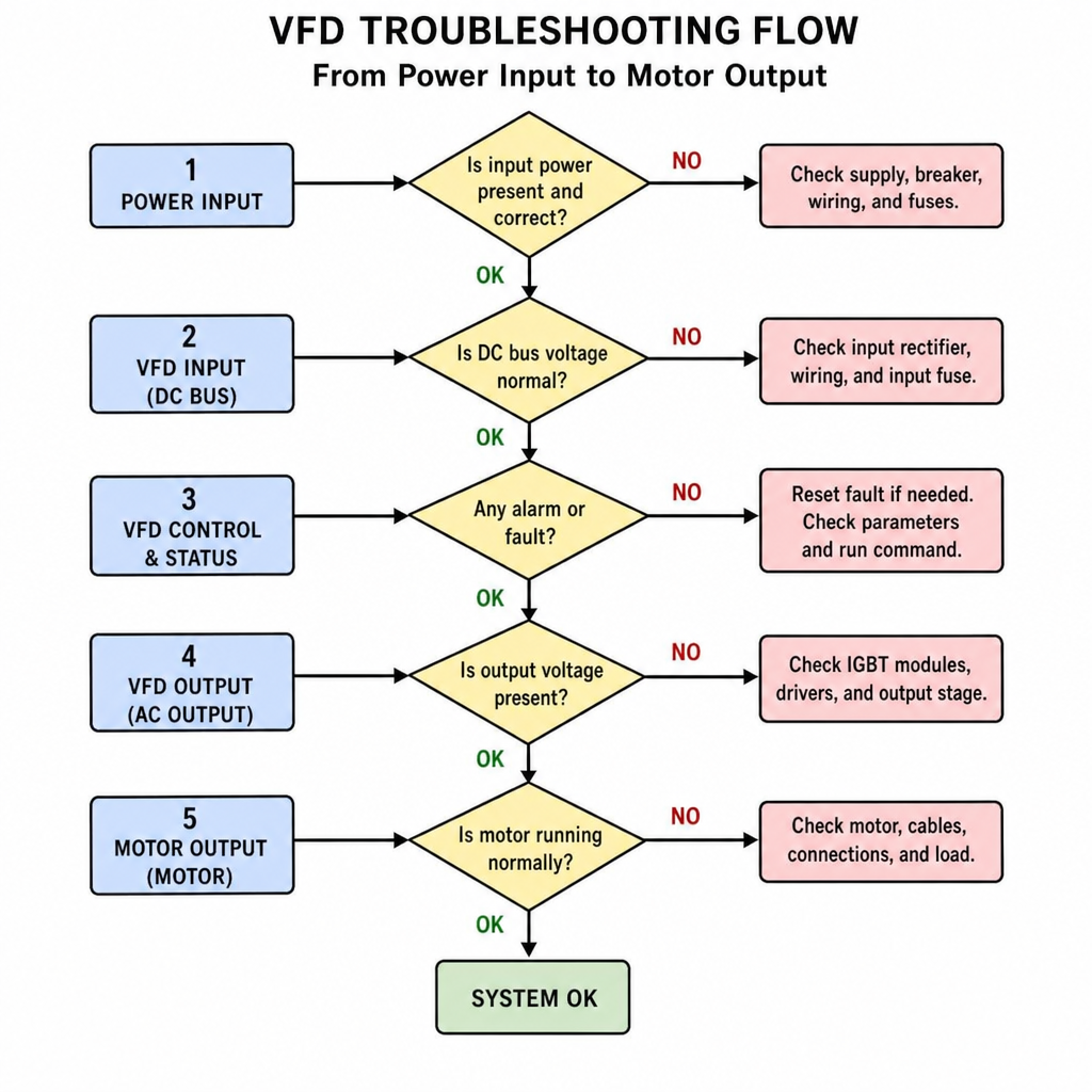
The best troubleshooting order moves from outside the drive to inside the drive. That sequence prevents unnecessary board, IGBT, capacitor, or fan replacement when the real cause is a blown fuse, bad motor cable, unstable supply, or incorrect parameter.
Check input power and mains conditions
For a phase loss or undervoltage-style alarm, measure input voltage phase-to-phase at the drive terminals, not only upstream at the disconnect. A loose lug, weak fuse holder, failing contactor, or single-phasing supply can disappear when measured at the wrong point. If the voltage is balanced upstream but not at the drive, the issue is likely in the wiring path.
For overvoltage alarms, look at when the trip occurs. If it happens during stopping or rapid deceleration, the motor may be regenerating energy back into the DC bus faster than the drive can absorb it. In that case, the fix may be a longer deceleration ramp, a properly sized braking resistor, or repair of the braking chopper circuit.
Separate motor faults from drive faults
A useful isolation test is to disconnect the motor leads at the drive, make them safe, and attempt a controlled no-motor run only if the manual and site procedure allow it. If the alarm clears with the motor disconnected, suspect the motor, cable, insulation, load, or output wiring. If the same overcurrent or short-circuit alarm appears with no motor connected, the fault may be inside the drive power stage.
Motor-side problems often include damaged cable insulation, moisture in junction boxes, grounded windings, incorrect motor data, or a mechanical load that is jammed or too heavy. Drive-side issues may involve IGBT modules, gate circuits, current sensors, or power boards, but those should be diagnosed after external causes have been ruled out.
When is replacement better than another reset?
Replacement becomes reasonable when measurements point to a failed component, the alarm repeats under safe unloaded tests, or inspection shows heat damage, contamination, swollen capacitors, failed fans, or damaged power electronics. Do not replace parts simply because a code mentions current, voltage, or temperature; those alarms can be symptoms of external process conditions.
Common replacement candidates include:
- Cooling fanswhen they are noisy, seized, intermittent, or unable to move air through the heatsink.
- DC link capacitorswhen visual inspection, age, or testing indicates deterioration; stored drives may also need proper capacitor reforming procedures.
- IGBT modules or power boardswhen output-stage faults remain after the motor and cable are disconnected and tested.
- Input rectifiers or fuseswhen a verified phase-loss condition is traced to the drive input section rather than the supply.
- Braking resistors or brake chopper componentswhen overvoltage trips occur during deceleration and the braking circuit does not operate correctly.
Compatibility matters. A replacement board or power module must match the drive series, frame size, voltage class, firmware requirements, and option configuration. Installing a near-match can create new alarms or leave the drive unsafe to run.
Process and environment often cause “drive” alarms
Many frequency converter trips are not caused by the drive itself. A pump running dry, a conveyor jam, a fan with dirty filters, or a valve that closes during ramp-up can all create current, torque, or temperature conditions that look like electrical failure at first glance.
Build a simple prevention routine around the alarms you see most often:
- Keep cabinet filters, heatsinks, and fans clean.
- Verify enclosure ventilation and ambient temperature during peak production.
- Tighten terminals during planned outages according to approved maintenance procedures.
- Trend fault logs so recurring trips are tied to shifts, recipes, loads, or utility events.
- Confirm motor nameplate data, acceleration time, current limits, and control signals after any parameter change.
The goal is not just to clear the display. It is to understand why the drive protected itself, correct the root cause, and return the process to service with less risk of a repeat trip.
Key takeaway
Frequency converter troubleshooting is fastest when it is disciplined: identify the alarm, make the equipment safe, check power and wiring first, isolate the motor, and then evaluate internal drive hardware. Common alarm codes point you in the right direction, but measurements confirm the real fault. With a clear sequence, maintenance teams can reduce downtime, avoid unnecessary parts replacement, and keep VFD-controlled systems running more reliably.