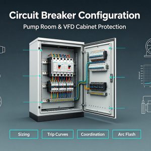
Circuit breaker configuration is more than “pick an amp rating and turn it on.” In real pump rooms, HVAC plants, and compressed-air systems, the breaker must protect cables and equipment, tolerate motor inrush, coordinate with upstream devices, and reduce downtime—especially inside a Variable Frequency Drive (VFD) cabinet where harmonics, switching, and sensitive electronics change the rules.
1) Start with the load: water pump, fan, compressor, and VFD cabinet differences
A good panel configuration begins by classifying the load and its starting/operating behavior:
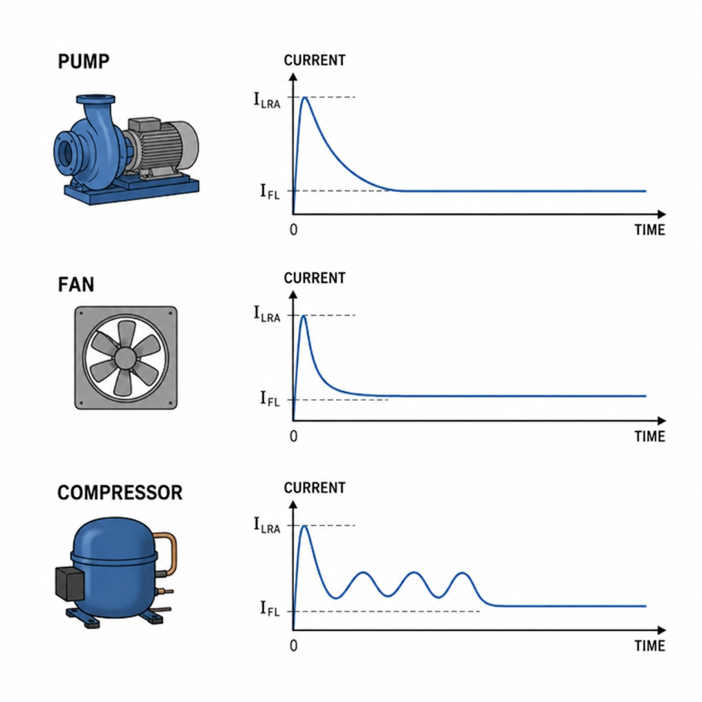
Water pump motors
- Often high inertia (especially vertical turbine or long piping systems)
- Common issues: long acceleration time, frequent starts, undervoltage events
- Key need: breaker setting for motor starting that permits inrush without sacrificing short-circuit protection
Fans and blowers
- Many are variable-torque loads (torque rises with speed)
- With VFD control, current can be smoother; across-the-line fans can still have large inrush
- Key need: appropriate instantaneous pickup (or short-time delay) to avoid false trips
Compressors
- Can have severe starting conditions (high head pressure, short cycling, mechanical load)
- Common issues: repeated starts, high locked-rotor current, nuisance trips from pressure switch chatter
- Key need: robust circuit breaker trip curve selection and control logic that limits starts/hour
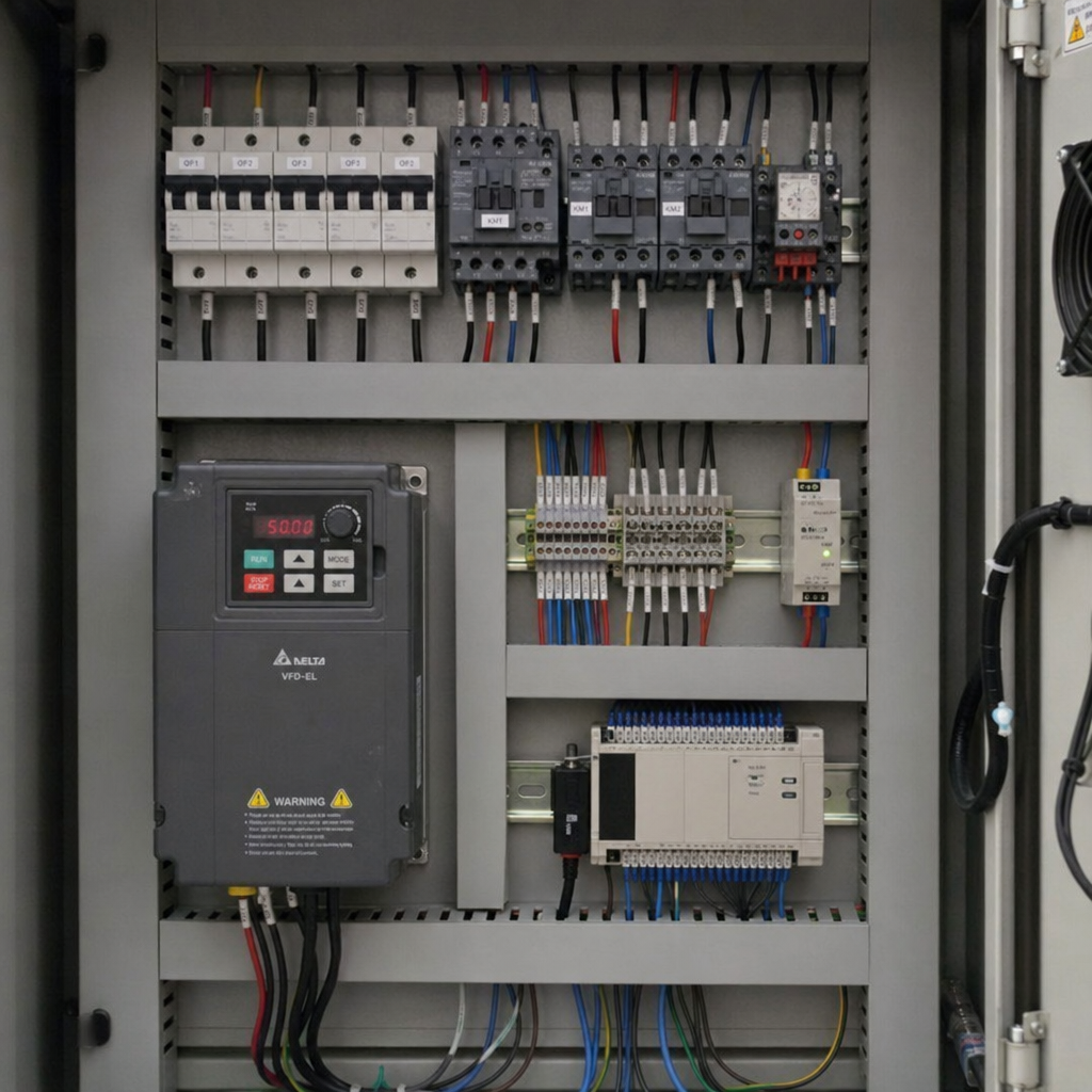
VFD cabinet (feeding a motor)
- Input side sees capacitor charging/inrush and harmonic currents
- Output side is not “normal sine-wave power” and typically is not protected by a standard breaker the same way
- Key need: correct line-side protection, grounding, and manufacturer-recommended devices
2) How to size a circuit breaker (the practical workflow)
When people ask how to size a circuit breaker, use a repeatable sequence:
- Collect nameplate & duty
- Motor kW/HP, voltage, FLA (full-load amps), service factor, ambient temperature, duty cycle, starts/hour, acceleration time.
- Select conductor size first
- Cable ampacity after derating (ambient, grouping, insulation temp rating).
- Then compare breaker amperage vs wire gauge chart as a sanity check—not as the design method.
- Choose breaker type and frame
- MCB for small branch circuits; MCCB for higher current/industrial; electronic trip when you need adjustable settings and coordination.
- Validate motor starting
- Ensure the breaker’s instantaneous element won’t trip on inrush.
- Confirm acceptable let-through energy for the cable/equipment (especially with high available fault current).
- Check fault duty
- Interrupting rating must exceed available short-circuit current at the installation point.
This process is the backbone of any circuit breaker setup for pumps, fans, and compressors.
3) MCCB vs MCB selection (and why it matters for motors & VFDs)
MCCB vs MCB selection is usually decided by current level, adjustability, and coordination needs:
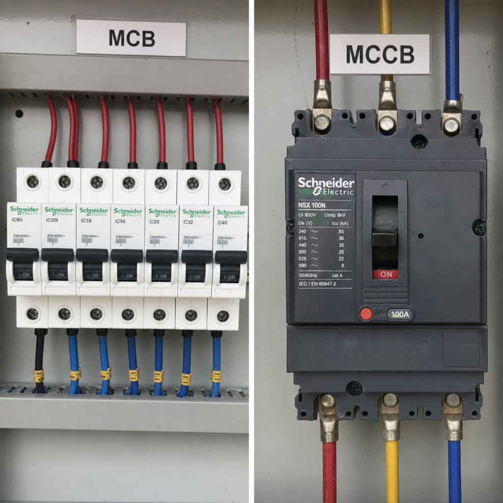
MCB (Miniature Circuit Breaker)
- Typical in commercial/light industrial panels
- Limited adjustment; trip curves like B/C/D
- Suitable for small motors and auxiliaries when fault levels and coordination demands are modest
MCCB (Molded Case Circuit Breaker)
- Higher current and higher interrupting options
- Often supports adjustable thermal and magnetic (or electronic) trip
- Better for motor feeders, compressors, and VFD mains where tuning and selectivity matter
Inside a VFD cabinet, MCCBs are common on the line side because you often need a higher interrupting rating and more intentional trip settings.
4) Short circuit current calculation method (and why you can’t skip it)
Der short circuit current calculation method determines the maximum fault current at the breaker terminals, which drives:
- Breaker interrupting rating (kAIC / Icu / Ics)
- Arc flash energy exposure
- Whether you need current-limiting protection
At minimum, you need:
- Utility transformer kVA and %Z (impedance)
- Feeder length and conductor size/material
- Any onsite generation contributions (gensets, PV with inverters, etc.)
If available fault current is high, a current-limiting fuse or a current-limiting breaker can drastically reduce equipment damage and help with breaker coordination study basics.
5) Trip curve selection: matching protection to motor behavior
Circuit breaker trip curve selection for MCBs
- B-curve: sensitive; often trips on motor inrush—rarely ideal for motors
- C-curve: moderate inrush tolerance—often workable for small pumps/fans
- D-curve: high inrush tolerance—commonly used for motors/transformers (where allowed by code and coordination)
For MCCB/electronic trip
Trip behavior is set by parameters, not letters. This is where coordination becomes real.
Thermal magnetic breaker adjustment guide (what you’re adjusting)
A thermal-magnetic breaker generally has:
- Long-time (thermal) pickup: protects against overloads
- Instantaneous (magnetic) pickup: protects against short circuits
For motor feeders, the common failure mode is setting instantaneous too low (nuisance trip on start) or long-time too high (cable not protected).
Electronic trip unit setting parameters (typical knobs)
- Ir (Long-time pickup): where overload protection begins
- tr (Long-time delay): how long overload is tolerated
- Isd (Short-time pickup) and tsd (Short-time delay): coordination band for selective tripping
- Ii (Instantaneous pickup): high-level short-circuit protection
- Optional: I²t ON/OFF (changes how strongly current affects trip timing)
These settings are the heart of a modern circuit breaker configuration for compressors and large pumps.
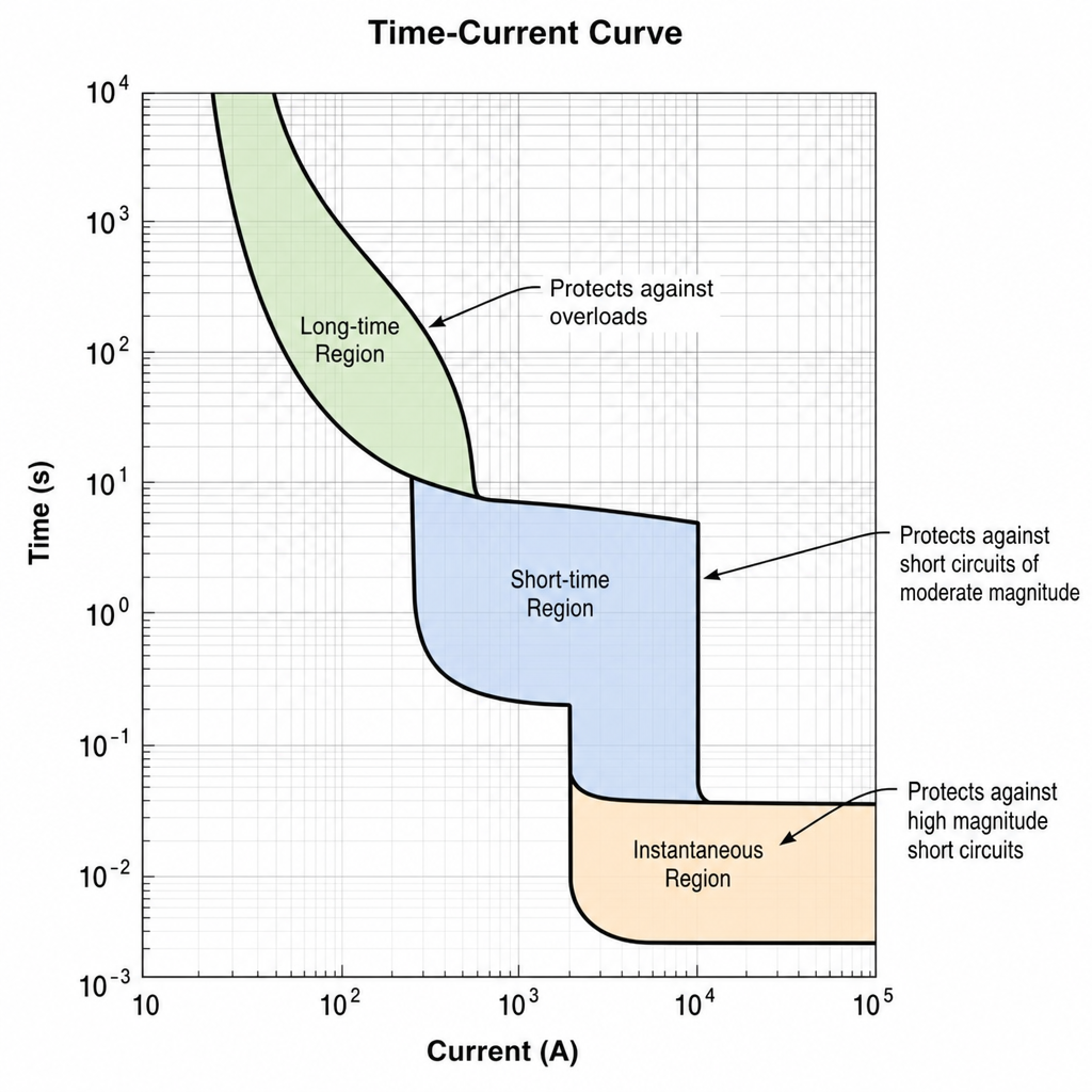
6) Breaker coordination study basics: selectivity vs coordination in protection
A basic coordination study ensures the device closest to the fault trips first, minimizing outages.
- Coordination: devices operate in a planned sequence under certain fault levels.
- Selectivity (often “full selectivity”): the downstream device trips first for all faults up to a defined maximum.
That distinction matters for selectivity vs coordination in protection: you might accept partial selectivity if full selectivity requires oversized breakers, higher costs, or unacceptable arc flash levels.
Practical coordination tips for motor systems:
- Use short-time delay on upstream breakers (when allowed) so downstream feeders clear faults first.
- Keep instantaneous on upstream high enough to avoid “both trip,” but not so high you exceed equipment withstand.
- In VFD mains, follow drive manufacturer guidance—some drives prefer fuses for let-through limitation and DC bus protection.
7) Ground fault protection settings (especially for wet areas and large feeders)
Ground fault protection settings are often overlooked in pump rooms—exactly where you want them right.
Key points:
- Ground-fault protection (GFP) is typically applied on larger feeders/services (and sometimes on large branch circuits).
- Too sensitive → nuisance trips from leakage, VFD filters, or moisture.
- Not sensitive enough → prolonged arcing/thermal damage.
For VFD systems, leakage current can be higher due to EMI filters and motor cable capacitance. Set GFP with real measurements when possible, and coordinate with upstream GFP to avoid cascading trips.
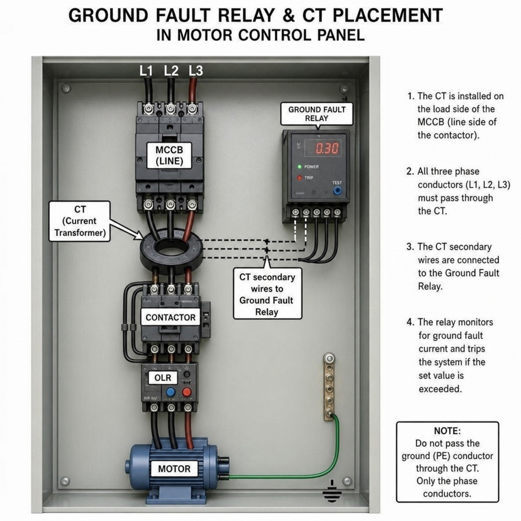
8) Arc flash risk assessment for breakers: configuration changes the hazard
Ein arc flash risk assessment for breakers is not just labeling—it’s influenced by settings:
- Raising instantaneous pickup or adding short-time delay can increase clearing time, raising incident energy.
- Current-limiting devices can reduce incident energy dramatically.
- Maintenance mode (if available) can temporarily reduce trip thresholds during energized work.
Actionable takeaway: coordinate protection and arc-flash performance together, not separately. If you tune settings for selectivity, revisit arc-flash results.
9) Standard breaker panel wiring diagram (what “good” looks like in practice)
A standard breaker panel wiring diagram concept for these loads typically includes:
- Main disconnect / main breaker
- Branch breaker (MCB/MCCB) → contactor/starter or VFD line input
- Overload relay (if across-the-line starter) sized to motor FLA
- Control transformer / control MCB
- Proper grounding and bonding (separate neutral/ground where required)
For VFD cabinets:
- Breaker (or fuses) on the line side
- Line reactor or EMC filter if specified
- VFD → motor output (often with dV/dt filter for long leads)
- Don’t put a standard breaker on the VFD output unless the manufacturer explicitly supports it and you understand the implications.
10) Troubleshoot nuisance breaker tripping (quick field checklist)
When you need to troubleshoot nuisance breaker tripping, diagnose in this order:
- Confirm when it trips
- At start (instantaneous/short-time issue) vs after minutes (overload/thermal issue)
- Measure actual current
- Inrush and running current per phase; look for imbalance
- Check mechanical load
- Pump binding, clogged impeller, high discharge pressure, compressor unloading failure
- Validate settings
- Long-time pickup not below running current
- Instantaneous not below starting inrush
- Verify wiring & terminals
- Loose lugs cause heat and thermal trips
- For VFDs
- Check DC bus precharge, input reactor, harmonic filter, and parameter settings
- Confirm line-side breaker type recommended by the drive OEM
11) Best circuit breaker brand comparison (how to choose without arguing brands)
A “best circuit breaker brand comparison” is most useful when you compare capabilities, not logos:
- Availability of frames and interrupting ratings suitable for your fault level
- Access to electronic trip units and coordination features
- Quality of published time-current curves and coordination software support
- Availability of accessories (shunt trip, UV release, aux contacts, communication)
- Service support and lead times in your region
Choose the breaker that meets the protection goals, coordination needs, and supply realities—not the one with the loudest marketing.
Conclusion: a configuration mindset that prevents downtime
A reliable circuit breaker configuration for a water pump, fan, compressor, or VFD cabinet comes from a disciplined workflow: size conductors, verify available fault current, select MCB/MCCB appropriately, tune trip settings to motor starting, apply coordination principles, and re-check arc-flash impact. If you do those steps—and document the final settings—you’ll reduce nuisance trips, limit damage during faults, and keep the rest of the plant online when something goes wrong.